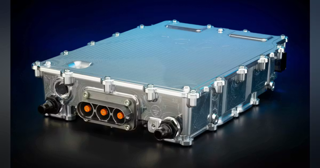

SiC MOSFETs operate at faster switching speeds, resulting in higher ripple-current frequencies and steeper voltage transitions that place greater stress on the DC-link capacitor. At the same time, the higher power densities possible with SiC mean that thermal management is increasingly critical to overall system performance. Together, these factors are forcing many electronics engineers to rethink DC-link capacitor design, requiring a review of the basic parameters for these components.
Parameters to Assess When Choosing DC-Link Capacitors
Several key parameters need to be considered when selecting DC-link capacitors for SiC inverters:
- Equivalent series resistance (ESR): This indicates the internal resistance within a capacitor that causes electrical losses and overheating, which is especially relevant when subject to high-frequency or high-voltage ripple currents that encounter resistance. Measuring and minimizing the capacitor’s ESR is key to ensuring a capacitor’s thermal stability and overall lifespan in the face of high-frequency SiC inverters.
- Equivalent series inductance (ESL): This refers to the capacitor’s ability to respond to high-frequency current transients. So, capacitors with high ESL may not effectively suppress the voltage spikes generated during fast switching events. As a result, low-inductance capacitor designs are of primary importance in SiC inverter applications.
- Ripple-current capability: This indicates how much AC current the capacitor can safely handle without excessive temperature rise. Designers must ensure that capacitor’s ratings exceed the expected operating ripple current under worst-case conditions.
- Thermal characteristics: Temperature has a significant impact on capacitor aging and reliability. Designers will need to review a capacitor’s ambient operating temperature and how it will respond to temperature rises caused by ripple-current losses.
- Expected lifetime: Most traction inverters are required to have a system lifetime exceeding 10 years. To confirm that they can perform up to standard for the duration of the inverter’s design life, the capacitors will need to undergo lifetime modeling and reliability analyses.
- Layout and parasitic effects: Important layout considerations include minimizing loop inductance between capacitors and power-switching devices, keeping conductor length to an absolute minimum, and ensuring symmetrical current paths. Optimizing these and other factors, such as capacitor placement and busbar design, enables peak performance within minimal volume.
The Relevant Capacitor Technologies for SiC Inverters
Traditionally, aluminium electrolytic capacitors or Al-caps dominated DC-link applications. These capacitors offer a relatively large capacitance in a small volume, while remaining relatively low cost.
However, their ESR profile and lifetime performance are often inadequate for high-frequency SiC inverters. They’re prone to overheating, and they tend to degrade markedly over their lifespan as a result of thermal stress and demanding operating conditions. As a result, film capacitors have become the go-to for DC-link capacitors in high-performance inverters. They provide low ESR and ESL, along with high ripple-current capability.
In addition, they exhibit self-healing properties. While localized damage can occur due to imperfections in the film, mechanical stress, or overheating, this doesn’t result in catastrophic failure. Instead, a film capacitor’s total capacitance will be slightly reduced following an overload event. Though it can lead to eventual failure through repeated dielectric breakdown over time, film capacitors are resistant to initial overloading from one standalone event.
The main drawback with film capacitors is their larger physical dimensions compared to aluminium electrolytic capacitors. This can pose some challenges on the increasingly crowded circuits boards used in SiC inverters.
In the context of these packaging constraints, multi-layer ceramic capacitors (MLCCs) are also often used in DC-link applications. These devices offer very low ESR and ESL, making them highly effective at the higher switching frequencies of SiC. They’re also highly compact, so many of them can be packed together in a small volume, enabling very high power-density inverters that can fit into tight spaces inside EV traction inverters.
However, reliability remains their primary limitation. Ceramic capacitors are very brittle and prone to cracking due to vibration, PCB flexing, mishandled assembly, or thermal expansion. They also experience piezoelectric effects, where AC current causes the material to repeatedly expand and contract, creating audible noise at the switching frequency. The fragility resulting from these factors is reflected in the high cost of ceramic capacitors, which make them uneconomical as the sole type of capacitor in the inverter.
In practice, the optimal solution for many EV SiC inverters is a hybrid approach that combines film capacitors with a cluster of ceramic capacitors (Fig. 2). This allows engineers to balance cost, performance, packaging, and reliability. The exact ratio of film to ceramic capacitors will depend on the expectations and requirements of the final inverter and EV platform.